Wiring diagram, howtos and diy wiki blog with HD images
Home
› Read Circuit Diagram / How To Read Circuit Diagrams 4 Steps Instructables : To interpret slds you first need to be familiar with the electrical symbols.
Read Circuit Diagram / How To Read Circuit Diagrams 4 Steps Instructables : To interpret slds you first need to be familiar with the electrical symbols.
Read Circuit Diagram / How To Read Circuit Diagrams 4 Steps Instructables : To interpret slds you first need to be familiar with the electrical symbols.. This instructable will show you exactly how to read all those confusing circuit diagrams and then how to assemble the circuits on a breadboard! It is much easier to draw these symbols than it is to draw pictures of components. The class letter shall be chosen from the. Truly expansive schematics should be split into functional blocks. Indicates that terminal is connected viaa plate in the relay box.
Recognizing names and values of schematic symbols. If an electrician misinterprets a A circuit diagram is like a map that shows electricity flows. Note that these lines represent conductors, which are the different wires that make up the circuit. How to read circuit diagrams.
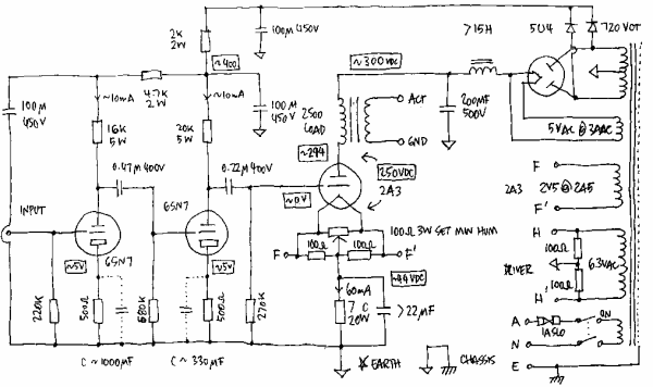
How To Read A Schematic Digikey from www.digikey.com To get began finding how to read circuit diagrams 4 steps ladder logic, chart., you are right to seek out our website which has a complete assortment of manuals listed. The power supply is shownat the top and the earth at the bottom to facilitate understanding of the current flow. Schematic reading tips identify blocks. An example of 66/6.6kv power substation single line diagram) we use universally accepted electrical symbols to represent the different electrical components and their relationship within a circuit or system. Try recognizing which sections are which, and following the flow of circuit from input to output. Circuit or schematic diagrams consist of symbols representing physical components and lines representing wires or electrical conductors. The ability to read electrical schematics is a really useful skill to have. Hydraulics schematic symbols are a basic component of hydraulic circuit.
Information about the device of the hydraulic system is shown on the hydraulic diagram using symbols.
Posted by james freeman | 01/15/2021. How to read circuit diagrams. You can read these circuits easily. Schematic diagrams are often read from left to right, like a book, with inputs on the left and outputs on the right. Schematic reading tips identify blocks. Electronic schematics represent the most detailed category of electronic drawings. To get began finding how to read circuit diagrams 4 steps ladder logic, chart., you are right to seek out our website which has a complete assortment of manuals listed. I'm an auto technician for over twenty years, i've always loved the electrical side of auto repair. An example of 66/6.6kv power substation single line diagram) we use universally accepted electrical symbols to represent the different electrical components and their relationship within a circuit or system. Information about the device of the hydraulic system is shown on the hydraulic diagram using symbols. This isn't a universal practice, but it's a good way to begin your analysis of the schematic. They serve as a map or plan for assembling electronics projects, and they are easy to read — far easier than understanding how the circuits they describe actually work. A drawing of an electrical or electronic circuit is known as a circuit diagram, but can also be called a schematic diagram, or just schematic.
There might be a section for power input and voltage regulation, or a microcontroller section, or a section devoted to connectors. To read circuit diagrams is a snap. A circuit diagram is like a map that shows electricity flows. A circuit diagram, or a schematic diagram, is a technical drawing of how to connect electronic components to get a certain function. How to read circuit diagrams.
How To Read Circuit Diagrams 4 Steps Instructables from content.instructables.com Knowing how to read circuits is a very useful skill that will help you out all the time. Truly expansive schematics should be split into functional blocks. Information about the device of the hydraulic system is shown on the hydraulic diagram using symbols. Electronic diagrams, prints, and schematics to read and understand an electronic diagram or electronic schematic, the basic symbols and conventions must be understood. To complicate things a little there is a reading of ieee 315, clause 22.2.1 actual versus intended function, which states if a part serves a purpose other than its generally intended one, the function actually performed shall be represented by the graphic symbol used on the schematic diagram; Later in this article series we will describe some simple hydraulic and pneumatic circuits composed of these circuit elements. Look around your schematic for horizontal and vertical straight lines in a variety of lengths and sizes. Alan winstanley, of everyday practical electronics magazine explains everything you need to know about understanding circuit diagrams properly.
Hydraulics schematic symbols are a basic component of hydraulic circuit.
I'm an auto technician for over twenty years, i've always loved the electrical side of auto repair. Our library is the biggest of these that have literally hundreds of thousands of different diagrams represented. It shows the components of the circuit as simplified shapes, and the facility and signal friends amongst the devices. Truly expansive schematics should be split into functional blocks. This instructable will show you exactly how to read all those confusing circuit diagrams and then how to assemble the circuits on a breadboard! Check for the complete loops that the conductors form, which allow electricity to flow throughout the circuit. Especially if you start messing around with building little electronics projects. They're like a map for building or troubleshooting circuits, and can tell you almost everything you need to know to understand how a circuit works. Below are some common illustrations of equipment located on fluids circuit diagrams, followed by descriptions of the most common elements. The reading process is far more comfortable than their actual work. A drawing of an electrical or electronic circuit is known as a circuit diagram, but can also be called a schematic diagram, or just schematic. The class letter shall be chosen from the. How to read circuit diagrams.
Circuit or schematic diagrams consist of symbols representing physical components and lines representing wires or electrical conductors. Try recognizing which sections are which, and following the flow of circuit from input to output. The class letter shall be chosen from the. Each electronic component has a symbol. This isn't a universal practice, but it's a good way to begin your analysis of the schematic.
Nissan Rogue Service Manual Sample Wiring Diagram Example How To Read Wiring Diagrams How To Use This Manual General Information from www.nirogue.com This isn't a universal practice, but it's a good way to begin your analysis of the schematic. The reading process is far more comfortable than their actual work. A car wiring diagram is a map. It is much easier to draw these symbols than it is to draw pictures of components. An example of 66/6.6kv power substation single line diagram) we use universally accepted electrical symbols to represent the different electrical components and their relationship within a circuit or system. I'm an auto technician for over twenty years, i've always loved the electrical side of auto repair. This instructable will show you exactly how to read all those confusing circuit diagrams and then how to assemble the circuits on a breadboard! To read and understand an electronic diagram or electronic schematic, the basic symbols and conventions must be understood.
Check for the complete loops that the conductors form, which allow electricity to flow throughout the circuit.
Especially if you start messing around with building little electronics projects. You can read these circuits easily. How to read circuit diagrams the circuit of each system from fuse (or fusible link) to earth is shown. To read circuit diagrams is a snap. It is much easier to draw these symbols than it is to draw pictures of components. A drawing of an electrical or electronic circuit is known as a circuit diagram, but can also be called a schematic diagram, or just schematic. A circuit diagram is like a map that shows electricity flows. To get began finding how to read circuit diagrams 4 steps ladder logic, chart., you are right to seek out our website which has a complete assortment of manuals listed. To read it, identify the circuit in question and starting at its power source, follow it to ground. Recognizing names and values of schematic symbols. Each electronic component has a symbol. Indicates that terminal is connected viaa plate in the relay box. Note that these lines represent conductors, which are the different wires that make up the circuit.