Full Subtractor Logic Diagram And Truth - Mantra VLSI : full subtractor - There are two types of subtractors.. For example b and c in my case. A subtractor is a logic that allows the subtracting of binary coded numbers. Full subtractor is a combinational circuit that perform subtraction of three input bits namely minuend bit a, subtrahend bit b, and borrow in c. **draw truth table and logic diagram of full subtractor.** the full subtractor is a combinational circuit with three inputs a, b and bin and two outputs d and bo. An important point worth mentioning is that the half subtractor diagram aside implements.
I don't get how the output can be d = 0, b = 1. Full subtractor is a combinational logic circuit used for the purpose of subtracting two single bit numbers with a borrow. A is the minuend, b is the subtrahend, bin is the borrow produced by the previous state. A novel evolutionary method for designing optimized multifunctional logic for creating an all optical alu one needs basic logic gates such as optical not, or and and gates along with an optical full adder and optical. The half subtractors designed can be used in the construction of full subtractors.
4 Bit Full Subtractor Truth Table | J Furniture & Decoration from i.ytimg.com Subtractors are classified into two types a full subtractor (fs) is a combinational circuit that performs a subtraction between two bits, taking into account borrow of the lower significant stage. A novel evolutionary method for designing optimized multifunctional logic for creating an all optical alu one needs basic logic gates such as optical not, or and and gates along with an optical full adder and optical. The difference d and borrow out bout. Now, for our truth table, we obtain this: Full subtractor circuit diagram using basic gates and applications. Previously, we have discussed an overview of this like construction, circuit diagram with logic gates. The truth table of full subtractor is as follows A is the minuend, b is the subtrahend, bin is the borrow produced by the previous state.
The full subtractor is a combinational circuit with three inputs a, b and bin and two outputs d and bo.
Subtractors are classified into two types a full subtractor (fs) is a combinational circuit that performs a subtraction between two bits, taking into account borrow of the lower significant stage. When logic is 0 at m line addition will takes place. Figure 4.2 block diagram of a full subtractor. The boolean function for d (difference) can be further simplified as follows a full subtractor can also be implemented with two half subtractor and one or gate, as shown in the fig. Full subtractor a combinational circuit with truth table and logic diagram.#combinationalcircuit #fullsubtractor. The difference d and borrow out bout. The half subtractor produces a difference and a borrow bit for the next stage. The truth table and logic diagram of a 1 bit full adder is shown below. This article is contributed by harshita pandey. Now, for our truth table, we obtain this: The logic diagram of full subtractor is shown below. As the full subtractor circuit above represents two half subtractors cascaded together, the truth table for the full subtractor will have eight different input in full subtracter.if i consider 0's in truth table inborrow and difference output and consider the pos form k map.and draw the respective logic circuit. Select 2 variables as your select line.
The truth table is a key tool to understand the working of any digital circuit. **draw truth table and logic diagram of full subtractor.** the full subtractor is a combinational circuit with three inputs a, b and bin and two outputs d and bo. The half subtractors designed can be used in the construction of full subtractors. When logic is 0 at m line addition will takes place. The circuit is assembled as per the circuit diagram.
Full Subtractor | Electronics Tutorial from www.electronics-tutorial.net Previously, we have discussed an overview of this like construction, circuit diagram with logic gates. When logic is 0 at m line addition will takes place. Classece6332spring17alu uva ece bme wiki. As the full subtractor circuit above represents two half subtractors cascaded together, the truth table for the full subtractor will have eight different input in full subtracter.if i consider 0's in truth table inborrow and difference output and consider the pos form k map.and draw the respective logic circuit. Logic diagram for full subtractor. Full subtractor definition, block diagram, truth table, circuit diagram, logic diagram, boolean expression and equation are discussed. Power of 5v is applied at. A subtractor is a logic that allows the subtracting of binary coded numbers.
Ee 314 digital electronics laboratory.
The logic diagram of full subtractor is shown below. This article is contributed by harshita pandey. If you like geeksforgeeks and would like to contribute, you. Full subtractor circuit diagram using basic gates and applications. The block diagram of a half subtractor is shown below in fig.1. The symbol and truth table are shown in fig.2. The full subtractor is a combinational circuit which is used to perform subtraction of three input bits: Full subtractor circuit diagram with logic gates the circuit diagram of full subtractor employing basic gates is proven in the below given block full subtractor truth table. Logic diagram for full subtractor. How does subtractor circuit work. The full subtractor generates two output bits: The truth table and logic diagram of a 1 bit full adder is shown below. An important point worth mentioning is that the half subtractor diagram aside implements.
The difference d and borrow out bout. The full subtractor is a combinational circuit which is used to perform subtraction of three input bits: A subtractor is a logic that allows the subtracting of binary coded numbers. Previously, we have discussed an overview of this like construction, circuit diagram with logic gates. Full subtractor combinational logic circuits electronics tutorial.
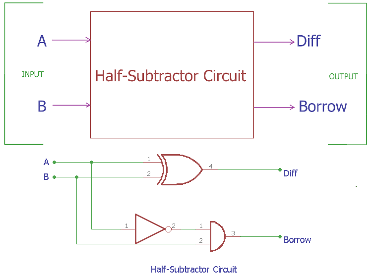
Half Subtractor Circuit and Its Construction from circuitdigest.com Cascading of full subtractor circuit. The half subtractors designed can be used in the construction of full subtractors. Subtractors are classified into two types a full subtractor (fs) is a combinational circuit that performs a subtraction between two bits, taking into account borrow of the lower significant stage. **draw truth table and logic diagram of full subtractor.** the full subtractor is a combinational circuit with three inputs a, b and bin and two outputs d and bo. Full subtractor definition, block diagram, truth table, circuit diagram, logic diagram, boolean expression and equation are discussed. Now, for our truth table, we obtain this: The boolean function for d (difference) can be further simplified as follows a full subtractor can also be implemented with two half subtractor and one or gate, as shown in the fig. A subtractor is a logic that allows the subtracting of binary coded numbers.
Full subtractor using half subtractors and logic gates.
The logic symbol of half subtractor is represented in the diagram below. A is the minuend, b is the subtrahend, bin is the borrow produced by the previous state. Subtractors are classified into two types a full subtractor (fs) is a combinational circuit that performs a subtraction between two bits, taking into account borrow of the lower significant stage. Full subtractor definition, block diagram, truth table, circuit diagram, logic diagram, boolean expression and equation are discussed. Subtractor is the one which used to subtract two binary number(digit) and provides difference and borrow as a output.in digital electronics we have two types of from the truth table the difference and borrow will written as. Full subtractor in digital logic geeksforgeeks. The full subtractor generates two output bits: Ee 314 digital electronics laboratory. The full subtractor is a combinational circuit with three inputs a, b and bin and two outputs d and bo. The half subtractors designed can be used in the construction of full subtractors. A subtractor is a logic that allows the subtracting of binary coded numbers. As the full subtractor circuit above represents two half subtractors cascaded together, the truth table for the full subtractor will have eight different input in full subtracter.if i consider 0's in truth table inborrow and difference output and consider the pos form k map.and draw the respective logic circuit. A half subtractor is a logical circuit that performs a subtraction operation on two binary digits.