Wiring diagram, howtos and diy wiki blog with HD images
Home
› How To Read Electrical Diagrams - Learn To Interpret Single Line Diagram Sld Eep / A ship electrical block diagram shows in simplified form the main inter relationships of the elements in a system, and how the ship system works or may be operated.
How To Read Electrical Diagrams - Learn To Interpret Single Line Diagram Sld Eep / A ship electrical block diagram shows in simplified form the main inter relationships of the elements in a system, and how the ship system works or may be operated.
How To Read Electrical Diagrams - Learn To Interpret Single Line Diagram Sld Eep / A ship electrical block diagram shows in simplified form the main inter relationships of the elements in a system, and how the ship system works or may be operated.. How to read and understand an electrical single line diagram? Such diagrams are often used to depict control systems and other complex relationships. This electrical diagram training course helps with understanding the operation, maintenance and appropriate trouble response to power system equipment begins with a detailed knowledge of and ability to read and interpret electrical prints. A ship electrical block diagram shows in simplified form the main inter relationships of the elements in a system, and how the ship system works or may be operated. Each physical component (i.e resistor, capacitor, transistor) has a unique schematic symbol.
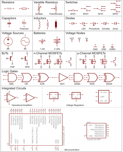
Here are some of the standard and basic symbols for various components for electrical schematics. In part 1 of this series, you've learned how to read and understand a wiring diagram of an. The ability to read electrical schematics is a really useful skill to have. Electrical schematics are the maps for designing, building, and troubleshooting circuits. For example, a few basic symbols common to electrical schematics are shown as:
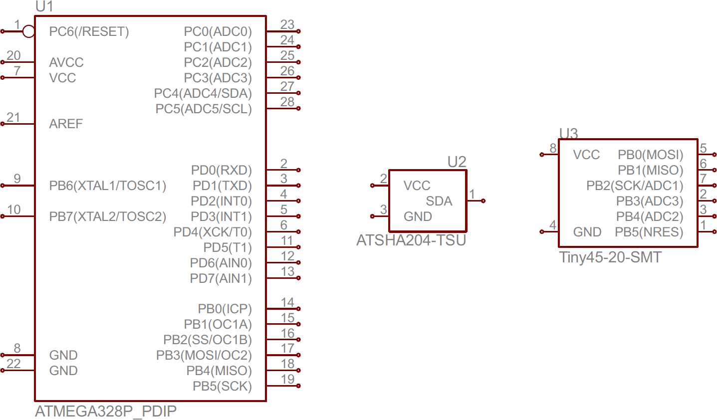
How To Read A Schematic Learn Sparkfun Com from cdn.sparkfun.com For example, a few basic symbols common to electrical schematics are shown as: An example of 66/6.6kv power substation single line diagram) we use universally accepted electrical symbols to represent the different electrical components and their relationship within a circuit or system. On it you can see some of the conventions used. Picture describes the main functions of an overcurrent. Basics 8 aov elementary & block diagram : Despite different standards of these types of drawings, you'll learn using actual industrial drawings and some plc wiring best practices. Each physical component (i.e resistor, capacitor, transistor) has a unique schematic symbol. Automotive electrical diagrams provide symbols that represent circuit component functions.
For example, a few basic symbols common to electrical schematics are shown as:
Learning how to read and understand schematics will be easy for beginners with recognizing basic schematic symbols. To interpret slds you first need to be familiar with the electrical symbols. We walk through some of the basics and most common symbols associated with reading an air conditioner wiring schematic or diagram.read all the tech tips, tak. How to read and understand an electrical single line diagram? A large number of free template, 50000+ vector symbols, making professional chart so easy. Use the legend to understand what each symbol on the circuit means. Basics 10 480 v pump schematic : Basics 8 aov elementary & block diagram : It will have one single line shown for bus (or cable) to represent all three phases. Scan over your schematics to figure out where your electrical currents are generated. A drawing of an electrical or electronic circuit is known as a circuit diagram, but can also be called a schematic diagram, or just schematic. Basics 9 4.16 kv pump schematic : A schematic can contain few or many symbols and connections and is normally read.
Schematic diagrams schematic diagrams document the connection points and construction methods of electrical and electronic circuits. To interpret slds you first need to be familiar with the electrical symbols. Note the switch symbol displays an open or closed circuit path, which is what an actual switch performs. This electrical diagram training course helps with understanding the operation, maintenance and appropriate trouble response to power system equipment begins with a detailed knowledge of and ability to read and interpret electrical prints. Basics 10 480 v pump schematic :
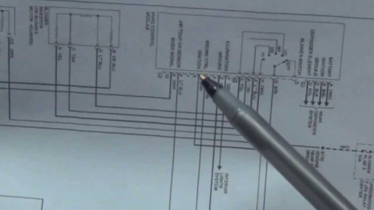
How To Read Wiring Diagrams Schematics Automotive Youtube from i.ytimg.com The ability to read electrical schematics is a really useful skill to have. Knowing how to read circuits is a very useful skill that will help you out all the time. Basics 10 480 v pump schematic : We walk through some of the basics and most common symbols associated with reading an air conditioner wiring schematic or diagram.read all the tech tips, tak. Learning how to read and understand schematics will be easy for beginners with recognizing basic schematic symbols. This is what we draw using autocad electrical. Scan over your schematics to figure out where your electrical currents are generated. A ship electrical block diagram shows in simplified form the main inter relationships of the elements in a system, and how the ship system works or may be operated.
Use the legend to understand what each symbol on the circuit means.
Creating flow chart, mind map, org charts, network diagrams, floor plan and more We walk through some of the basics and most common symbols associated with reading an air conditioner wiring schematic or diagram.read all the tech tips, tak. Electrical schematics are the maps for designing, building, and troubleshooting circuits. To start developing your schematic reading abilities, it's important to memorize the most common schematic symbols. Learning how to read and understand schematics will be easy for beginners with recognizing basic schematic symbols. On it you can see some of the conventions used. But sometimes, designers make some exceptions to have a better layout such as this page. Look for circles filled with symbols that signify the power source. How to read and understand an electrical single line diagram? A diagram that represents the elements of a system using abstract, graphic drawings or realistic pictures. Picture describes the main functions of an overcurrent. Note the switch symbol displays an open or closed circuit path, which is what an actual switch performs. Knowing how to read circuits is a very useful skill that will help you out all the time.
Use the legend to understand what each symbol on the circuit means. To read and interpret electrical diagrams and schematics, the reader must first be well versed in what the many symbols represent. Basics 14 aov schematic (with block included) How to read and understand an electrical single line diagram? A single line can show all or part of a system.
How To Read A Schematic Learn Sparkfun Com from cdn.sparkfun.com Learning how to read and understand schematics will be easy for beginners with recognizing basic schematic symbols. An electrical schematic is a logical representation of the physical connections and layout of an electric circuit. A car wiring diagram is a map. To read it, identify the circuit in question and starting at its power source, follow it to ground. Electrical schematics are the maps for designing, building, and troubleshooting circuits. Circuit or schematic diagrams consist of symbols representing physical components and lines representing wires or electrical. An example of 66/6.6kv power substation single line diagram) we use universally accepted electrical symbols to represent the different electrical components and their relationship within a circuit or system. On it you can see some of the conventions used.
Basics 9 4.16 kv pump schematic :
Scan over your schematics to figure out where your electrical currents are generated. Refer to the figure, an electrical wiring diagram is surrounded by the rectangular box. Basics 13 valve limit switch legend : This is what we draw using autocad electrical. The power supply is shown at the top and the earth at the bottom to facilitate understanding of the current flow. This electrical diagram training course helps with understanding the operation, maintenance and appropriate trouble response to power system equipment begins with a detailed knowledge of and ability to read and interpret electrical prints. Note the switch symbol displays an open or closed circuit path, which is what an actual switch performs. An electrical schematic is a logical representation of the physical connections and layout of an electric circuit. An example of 66/6.6kv power substation single line diagram) we use universally accepted electrical symbols to represent the different electrical components and their relationship within a circuit or system. This chapter discusses the common symbols used to depict the many components in electrical systems. Look for circles filled with symbols that signify the power source. Circuit or schematic diagrams consist of symbols representing physical components and lines representing wires or electrical. Exactly like reading a book!