Wiring diagram, howtos and diy wiki blog with HD images
Home
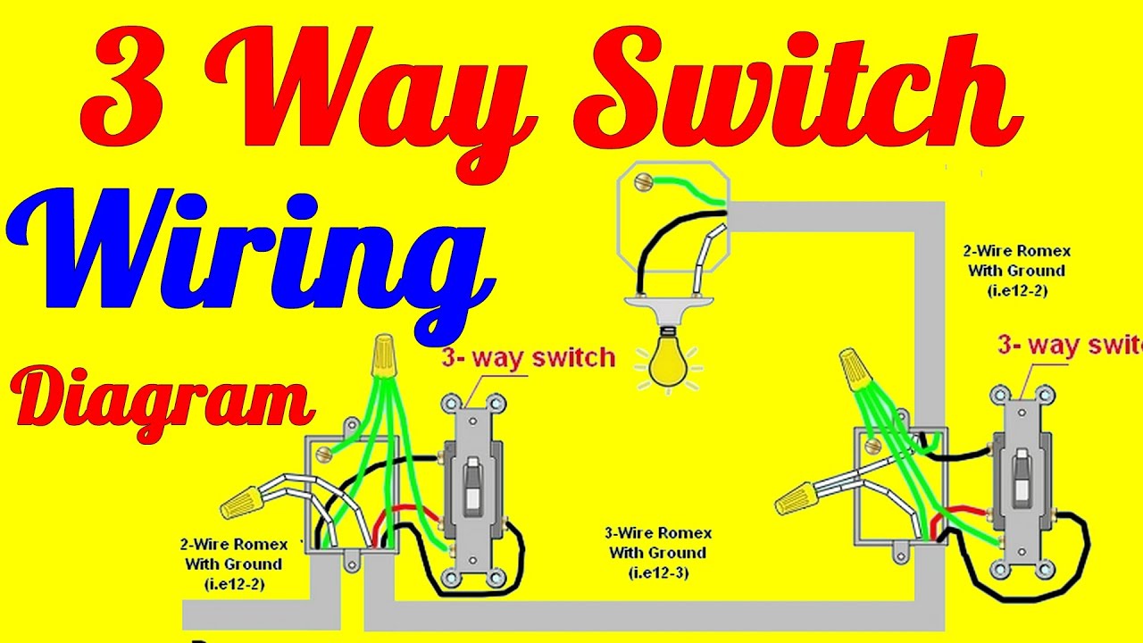
› 3 Way Switch Wiring Diagram With 2 Lights / Wiring 4 Lights 3 Way Switch | www ... | 3 way switch wiring, Light switch wiring, Three way switch : The other two wires can attach to either of the identical terminals.
3 Way Switch Wiring Diagram With 2 Lights / Wiring 4 Lights 3 Way Switch | www ... | 3 way switch wiring, Light switch wiring, Three way switch : The other two wires can attach to either of the identical terminals.
3 Way Switch Wiring Diagram With 2 Lights / Wiring 4 Lights 3 Way Switch | www ... | 3 way switch wiring, Light switch wiring, Three way switch : The other two wires can attach to either of the identical terminals.. 2 way lighting circuit, 2 way switch, 2 way switch. With these diagrams below it will take the guess work out of wiring. The hot from the power source is spliced through both fixtures and terminates at the common terminal of sw1 via cable c3. More lights can be added to this circuit by duplicating the wiring shown here for each additional fixture. It is only needed one time, as all other lights (only limited by wattage of switch) are run by 14/2 wire.
Here the neutral connects to the light f1 and is spliced through to light f2. The neutral is spliced to the white wire feeding the first fixture, via cable c1,where it is spliced to the neutral of both lights. Saved by lowering eletricity bills everyware. Refer to the illustrations below for doing. 3 way light switch with power feed via the light (two lights) the power, cable c1, joins the circuit at the light fixture f1.
Light Switch Wiring Diagram : 2 Way Switch With Electrical Outlet Wiring Diagram Light Switch ... from 4.bp.blogspot.com The neutral is spliced to the white wire feeding the first fixture, via cable c1,where it is spliced to the neutral of both lights. The (orange) red wire is part of the 14/3 wire they used in diagram. Standard 2 way switch wiring. Instructions for dimmer switch wiring. A 2 way switch wiring diagram with power feed from the switch light : Saved by lowering eletricity bills everyware. Refer to the illustrations below for doing. The hot source is connected to the common terminal of sw1.
The grey wire in cable 'd' is a switched live and the blue wire in cable 'c' and black wire in cable 'd' are permanent lives and thus should be marked with brown sheathing at each end as shown.
In this diagram, the electrical source is at the first switch and the light is located at the end of the circuit. The black and red wires between sw1 and sw2 are connected to the traveler terminals. Electrical switch wiring 3 way switch wiring wire switch electrical wiring diagram electrical layout electrical outlets outlet wiring cheap electricity three way switch. You can observe in the schematic that both the com terminals are connected together. With these diagrams below it will take the guess work out of wiring. Saved by lowering eletricity bills everyware. 3 way switched outlet wiring. Turn off the branch circuit from your electrical panel and add all the electrical boxes required. Pick the diagram that is most like the scenario you are in and see if you can wire your switch! Wiring 3 switches and 2 lights. 3 way switch diagrams for multiple light fixtures: In this diagram, two 3 way switches control a wall receptacle outlet that may be used to control a lamp from two entrances to a room. Fig 2 below shows how we achieve this configuration.
This drawing shows the wiring for multiple lights in a 4 way switch circuit with the source and fixtures coming before the switches. Put a piece of tape on the wire that goes to the common terminal screw. In this diagram, two 3 way switches control a wall receptacle outlet that may be used to control a lamp from two entrances to a room. Wiring diagram 3 way switch with light at the end. Refer to the illustrations below for doing.
3 Way Switch Wiring Diagrams How To Install - YouTube from i.ytimg.com The power source comes from the fixture and then connects to the power terminal. Click the icons below to get our nec ® compliant electrical calc elite or electric toolkit, available for android and ios. The source comes into the light, the switch then is the last box on the circuit. This might seem intimidating, but it does not have to be. The black and red wires between sw1 and sw2 are connected to the traveler terminals. This drawing shows the wiring for multiple lights in a 4 way switch circuit with the source and fixtures coming before the switches. Refer to the illustrations below for doing. The neutral is spliced to the white wire feeding the first fixture, via cable c1,where it is spliced to the neutral of both lights.
The (orange) red wire is part of the 14/3 wire they used in diagram.
Instructions for dimmer switch wiring. Put a piece of tape on the wire that goes to the common terminal screw. 3 way switch diagrams for multiple light fixtures: The other two wires can attach to either of the identical terminals. More lights can be added to this circuit by duplicating the wiring shown here for each additional fixture. 3 way switch wiring diagram. Option #2 is for power into the first switch but then wires run separately from the first switch to the light. Here the neutral connects to the light f1 and is spliced through to light f2. 10.10.2018 10.10.2018 3 comments on clipsal light switch wiring diagram australia. 3 way light switch with power feed via the light (two lights) the power, cable c1, joins the circuit at the light fixture f1. Click the icons below to get our nec ® compliant electrical calc elite or electric toolkit, available for android and ios. In this diagram, the electrical source is at the first switch and the light is located at the end of the circuit. In this diagram, two 3 way switches control a wall receptacle outlet that may be used to control a lamp from two entrances to a room.
Fig 2 below shows how we achieve this configuration. Two way light switching (3 wire system, new harmonised cable colours) note: Take a closer look at a 3 way switch wiring diagram. This might seem intimidating, but it does not have to be. The hot from the power source is spliced through both fixtures and terminates at the common terminal of sw1 via cable c3.
3 way switch | Three way switch, 3 way switch wiring, Three way switch wiring from i.pinimg.com The source comes into the light, the switch then is the last box on the circuit. Two way light switching (3 wire system, new harmonised cable colours) note: You can observe in the schematic that both the com terminals are connected together. 2 way lighting circuit, 2 way switch, 2 way switch. The neutral is spliced to the white wire feeding the first fixture, via cable c1,where it is spliced to the neutral of both lights. The power source comes from the fixture and then connects to the power terminal. In this diagram, two 3 way switches control a wall receptacle outlet that may be used to control a lamp from two entrances to a room. The grey wire in cable 'd' is a switched live and the blue wire in cable 'c' and black wire in cable 'd' are permanent lives and thus should be marked with brown sheathing at each end as shown.
3 way light switch with power feed via the light (two lights) the power, cable c1, joins the circuit at the light fixture f1.
More lights can be added to this circuit by duplicating the wiring shown here for each additional fixture. The grey wire in cable 'd' is a switched live and the blue wire in cable 'c' and black wire in cable 'd' are permanent lives and thus should be marked with brown sheathing at each end as shown. The other two wires can attach to either of the identical terminals. The black and red wires between sw1 and sw2 are connected to the traveler terminals. Put a piece of tape on the wire that goes to the common terminal screw. In this diagram, two 3 way switches control a wall receptacle outlet that may be used to control a lamp from two entrances to a room. It is only needed one time, as all other lights (only limited by wattage of switch) are run by 14/2 wire. In this diagram, the electrical source is at the first switch and the light is located at the end of the circuit. The hot from the power source is spliced through both fixtures and terminates at the common terminal of sw1 via cable c3. You can observe in the schematic that both the com terminals are connected together. Instructions for dimmer switch wiring. Option #2 is for power into the first switch but then wires run separately from the first switch to the light. Two way light switching (3 wire system, new harmonised cable colours) note: